Page 3
With the elevators closed out the focus of the work now turns to the trim tab. The plans and manual discuss two different trim systems, one mechanical that uses compression springs and sliding fittings on the elevator control rod in front of the elevator bob weight, the other an electrical system which uses a MAC servo motor and a movable trim tab which is cut from the inboard aft end of the left elevator half. I chose to go with the electric servo installation and this page will outline the process. |
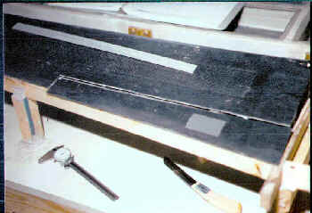 |
Work starts on the trim tab Now that the elevators are closed the work can continue on the trim tab. The first step is to cut the part from the elevator, using a Dremel tool with a cutoff wheel to perform the task. The positioning of the tab was all done prior to closing the elevator, as locating holes were bored into the top skin at the corners to define the outline... all that was needed was to connect the dots and follow the line with the cutting tool. The only difficult part was insuring that the cuts were made perpendicular to the chord line, but by using a dial caliper to insure that the layout on the bottom matched the top I was able to guarantee proper cut lines by duplicating dimensions from top to bottom. Here you see the trim tab as it was just cut from the elevator. |
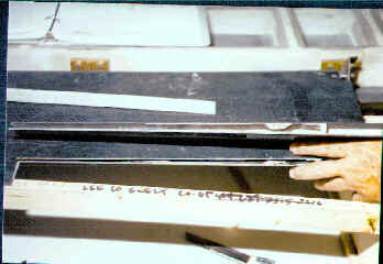
The view along the edge As you can see there isn't very much room to work inside the trim tab, so I'm very pleased that I chose to install all the capstrips and spars prior to detaching it from the elevator. Now there is enough 'meat' there to install the hinges without too much difficulty or need for additional buildups and the shape of the airfoil has been maintained. |
 |
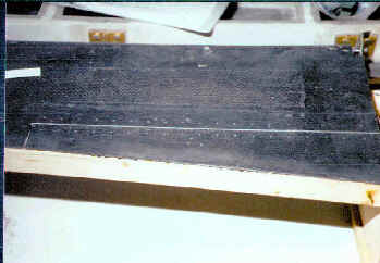 |
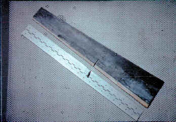
Hinge attach holes are drilled By locating the hinge aligned with the cut line between the elevator and the trim tab the holes are transferred from one to the others. The trim tab was taped into position, the hinge aligned and initial holes were drilled at the ends of the hinge. Clecos were installed into the end holes to keep the entire affair aligned during the drilling process, and here you see the end result. |
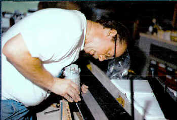
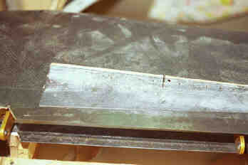
Clearance cutting the hinge line Now that the hinge can be installed into the mating parts the process of cutting out the clearance required between them for the hinge body begins. Here I am using a laminate trimmer (basically a small router) with a straight cutting trimming cutter installed to cut my perfectly straight line. The aluminum straightedge was clamped to the elevator and used as the guide for the trimmer base. It took several passes to get the hingeline opened up far enough, but it made more sense to achieve that perfect fit a little at a time rather than taking out all the material in a single pass. |
 |
 |
Straightening out an 'oops!' While cutting back the trim tab clearance area on the bottom of the elevator my laminate trimmer decided to slip deeper into its base without my noticing and I wound up cutting away a part of the hingeline area on the top skin that I'd so carefully prepared earlier. This little faux pas wound up costing several hours and some unnecessary fooling around to repair the damage, but it all turned out okay in the end. I covered the top of the hinge with some very thin packaging tape to use as a release agent and then did a 1-BID layup (using very thin glass cloth typically used on model airplanes) on the hinge half to provide support to the repair area. This would insure that my repair didn't interfere with the fit of the hinge and also helped lower the hinge another couple thousandths relative to the top skin. With the layup applied and the hinge clecoed in place I used a 50/50 flox/micro mixture to replace the damaged carbon fibre area and after it was done the only difference was that that area showed a small red line instead of the black carbon fiber appearance of the rest of the elevator. |
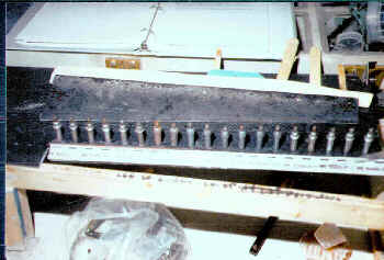
| You can also see the piece of foam that was added to the inner bottom skin of the trim tab (it's up there sitting on the elevator). It needed to be shaped in such a way that it would keep the gap between the LE of the trim tab and the TE of the elevator constant thoughout the range of the trim tab's travel. It was kind of a tricky prospect as the radius that needed to be defined centered on the hingeline and because the tab was thicker inboard than outboard it was larger at the inboard end than at the outboard end. It also needed to be thin enough at the outboard end so it didn't interfere with the hinge attachment to the upper skin. Suffice it to say that there will be far less left of that foam after shaping than what is seen here. | |
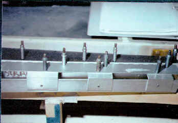
A fixture to shape the foam leading edge Rather than battle the part on the elevator I chose to fabricate a small fixture out of some aluminum angle and flat stock that would define the radius along the trim tab's lower leading edge. It was basically a long box open at one corner (shaped much like a letter "C") that mounted to the hinge on the top and butted up against the trim tab's lower skin and aligned with the transition to the foam on the bottom. It was mostly pop riveted together but clecos were again used for the initial assembly. Clecos were also used to attach it to the trim tab so it could be removed easily as the shaping progressed. Basically it was a replacement for the elevator lower trailing edge, just much more compact and easier to deal with. |
 |
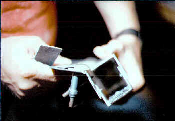 |
It really worked! Here is the view of the end of the fixture/trim tab assembly, and it clearly shows that the fixture did the job of transferring that radius accurately. This is looking at the outboard end and you can see how the fixture fit up against the bottom skin and defined the radius as it was rotated through its range of travel... I had removed the fixture from the tab once its shape had been locked in and reinstalled it rotated upward so I could remove the material from the foam's leading edge back. Initial shaping was done with an Exacto knife with a #11 blade and once all the foam was removed I put a length of 180 grit sandpaper between it and the fixture to smooth to the finished shape. After the shaping was done the trim tab was temporarily installed onto the elevator and checked for fit. With everything fitting up properly a thin coating of micro was applied to the foam and a single BID layer of model airplane cloth was applied. |
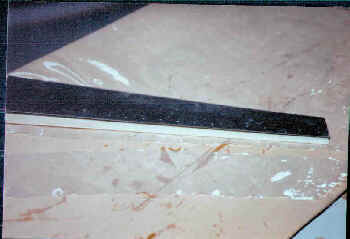
Foam shaping completed The inner surface of the foam was shaped with some sandpaper to allow for clearance between it and the hinge and here you see what the tab looked like with the foam in its finished state. This shot was taken just before the glass cloth was applied which added the final structure to the foam and further tied it to the tab both inside and out. There will still be some body work required, but not very much thanks to the accuracy of the shaping of the foam. (It took about an hour to build the fixture but only about 15 minutes to actually get the foam shaped... personally I'm pleased that I chose to go this route, as it really worked out well.) |
 |
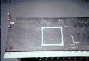 |
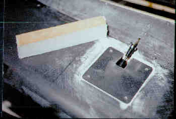
Truing the access panel gap When the access panel was cut from the elevator, the gap varied slightly around the corner radii so it was necessary to apply some filler to get it all trued up around the entire perimeter. Pictured here is the panel itself with several layers of duct tape applied around the edges to define the .020" gap required to get it all looking neat and tidy. |
Ready to install the hinge The glass cloth has been applied and the control horn is mounted to the hinge. A small notch was required in the lower leading edge to clear the control horn and a small amount of foam had to be removed from the interior to get the hinge/control horn assembly inside. The control horn was permanently mounted to the hinge with a pair of rivets and provisions were made for a single screw that would also be installed which would fasten the horn to the tab's top skin. |
 |
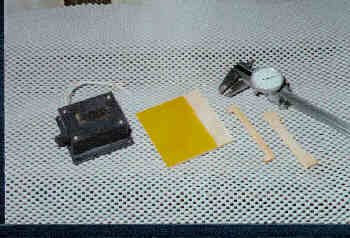 |
Preparing a servomotor mount The kit was supplied with a single piece of 1/8" thick phenolic sheet as a mount for the trim servomotor, but a suggestion posted in the Lancair Mail was to modify that pad and create, instead, a mount that allowed the front of the motor base to be captured by additional phenolic layers rather than having to bolt the front down. The primary reason was that the front bolts would be nearly inaccessible and getting the nuts in and out would be very difficult. Deciding to go this route required the purchase of a sheet of 1/8 phenolic and the parts shown here were fabricated from it. |
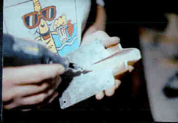
| The mounting base (left phenolic part) is larger than the actual motor base by 1/4" all around to allow the attachment of the retaining layers. The middle phenolic part is cut back to allow the front of the motor base to extend into it and then the rightmost part is the top layer which captures the front of the motor base. All three parts were glued together using Hysol structural adhesive and 4-40 bolts were added at the front corners to insure that the thing never came apart. Holes were drilled into the rear of the base and countersunk to accept the 6-32 flathead machine screws that would secure the motor to the new base. The heads of these screws were ground to have flat edges and then potted into the bottom of the phenolic base with a Hysol/flox mixture so they wouldn't turn when the locknuts that secure the motor were installed. Even though the inner carbon fiber skins had been removed and the trim motor was installed as far forward as possible, the body of the motor still wanted to contact the interior of the access panel so the large phenolic mounting plate was machined down to a wedge shape that was only 1/16" thick at the aft end and tapered to full 1/8" thickness at the front (spar) end. Once the proper fit had been achieved the entire unit was mounted to the inside top skin with Hysol. | |
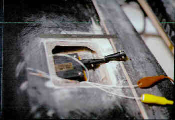
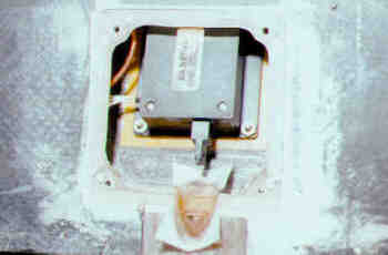
Sizing the trim control pushrod As can be seen in this photo, the nylon clevises supplied with the MAC servo were slightly longer than the installation would allow to be used without some modification, as they overlapped when the trim motor actuator and trim tab both were put in the center position. I chucked them into the drill press and used a razor saw to cut about 3/8" off of each clevis which would allow enough of the threaded pushrod to show so that locknuts could be run up against the clevises to lock them into position. The alligator clips visible were attached to a 9.6 volt drill battery and simply reversed to change direction on the servo. A circular relief was ground into the edge of the access area to allow the pushrod assembly to move without binding. |
 |
 | Streamlining the pushrod With the trim tab operating to the specifications in the manual (travel both up and down measured to 30 degrees) I decided that building a fairing over the pushrod would be the next order of business. To accomplish this task I chose to attach a piece of high density foam to the access panel which I could shape and use as an interior mold for the fairing. Before attaching the foam with thick CA (cyanoacrylate adhesive, or thick Super Glue) I used a pencil to outline the range of travel of the top of the control horn on the side of the foam. I then attached the foam to the access panel and started the shaping process with some 40 grit sandpaper. |
The form is shaped This shot shows the access panel with the foam attached and formed to the desired shape which would fair in the control horn and pushrod. The aft of the foam was cut so the opening of the fairing would mate to the lower surface of the trim tab when deflected to the full down position. The corners were shaped to pleasing curves and it's time to apply the layups. The area under the foam aft of the access panel had a few additional layers of glass cloth applied and then the trough for the mounting ears of the fairing was cut using a router with a straight cutter. A layer of release tape was applied to that trough prior to laminating the foam. |
 |
 |
Foam removal and cleanup I used a 2-BID layup over the foam and lapped it about 1/2" onto the access panel to insure it was permanently attached. As you can see in this photo, a Dremel Tool with a small grinding bit was used to eliminate the last of the foam from the interior of the fairing. The bulk of the foam had been removed with a pocket knife and the grinder used primarily for final cleanup and smoothing and shaping of the interior. |
Laminating the clearance notch In order to provide proper clearance between the servomotor pushrod and the elevator structure a small semi-circular area was ground out of the aft spar and capstrip that closed out the servo area. This exposed the foam that was used to create the spar and also created a hole behind it in the clearance area for the pushrod shroud. To re-cover this area a small 1-BID patch was applied and subsequently trimmed to fit, providing a nice smooth tunnel in which the push rod would move. |
 |
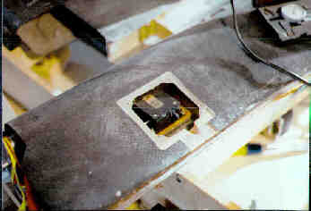 |
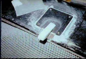
Finished trim motor installation With the small 1-BID closeout trimmed flush and the area around the access panel sanded smooth, the installation of the trim tab and its controlling mechanism was nearing completion. I noticed that the filler which I'd used around the access panel to clean up the outline was chipping and so I started asking some questions about it... thanks to my friends on AVSIG at Compuserve I learned that using polyester filler (ie, Bondo) over epoxy could result in less than 100% adhesion. I used a fingernail under the remaining Bondo and found that I could chip it out with very little effort. |
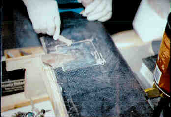
Replacing the Bondo I used a chisel to remove the last of the Bondo from the area surrounding the access panel cutout and here you see me replacing it with home-made epoxy/microballoon filler. This stuff stuck like grim death and resulted in a nice fine line all around the access panel. Release tape was applied to the edges of the panel before this filler application, of course. |
 |
 |
Rivet bucking holes The hinge was to be attached to both the trim tab and the elevator with rivets, but there was no room to get a rivet squeezer into either component so a different approach needed to be taken. Using the rivet holes as guides additional holes were drilled through the opposite skins to afford access to the ends of the rivets to facilitate the use of a bucking tool. The notch you see is for the control horn and the large hole next to it is to provide access to the small locknut that will be used to secure the control horn to the hinge. The plans called for two machine screws to hold the control horn, but considering the close quarters I chose to use a single screw surrounded by a pair of rivets. |
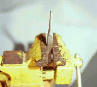
Poor man's bucking bar This is a modified center punch that we used as a bucking bar for setting the rivets. By placing the bar in the vise I was able to insert and align the rivets and hold the part while my building buddy wielded a hammer and another modified punch to form the rivets. I suppose it could have been done as a one man operation, but having two people sure made it go much smoother. These were the first rivets I'd ever formed without benefit of the rivet squeezer and they all turned out just fine. I recommend this approach highly. |
 |
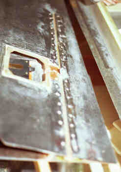 |
Filling the holes once again it was time to mix up some filler, this time to close all the holes that were used during the forming of the rivets. Since I was replacing some structure here I chose to use epoxy mixed with 50/50 flox/micro, which gave me a much tougher filler than the straight microballoon mixture would have. |
With the completion of the trim tab it is time to go back to the horizontal stab and finish the closeout on it. There is still a very important step remaining on the elevator, that being the provision of the actual lead weights to balance the control surfaces. I've chosen to hold off on this activity until the horizontal tail is assembled to the fuselage and the body work begins on that part of the structure. This way the stab will be permanently affixed to the fuselage and the pushrod can actually be attached to the elevators giving me a truer picture of the actual weight that will be required to balance the complete elevator. The elevator halves will be individually statically balanced first, of course, as the left one will undoubtedly require more weight thanks to the trim tab, and then the entire structure can be balanced as a whole. |
|
... Closing Out the Stabilizer |