Page 4
With all the work completed on the elevators and the trim tab it's now time to get back to that pesky stabilizer and put on its finishing touches. The most critical and time consuming aspects of its construction are behind us and all that's left is to close it out. This is not to imply that there's not a significant amount of stabilizer work yet left to be done, but after dealing with the early parts of the learning curve, this final assembly should progress rather smoothly. I've not made any mention of time consumed to this point, but my records show that a total man hour investment of some 400+ hours have elapsed since the project began, and if we weren't to count the duplicate hours caused by a second body working in the shop, the actual hour count would be closer to 250. This includes not only the work on the tail, but some 35 hours of work that were expended on getting started with the brackets and fittings while debating about the proper path to take with the elevator spars. That work will be presented on another page soon to be added to the site... but for now, let us continue with laying this horizontal tail to rest....... |
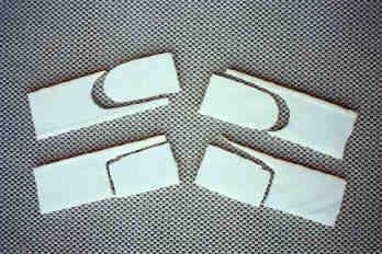
What on earth?? These are 4 pieces of high density foam that I used to take patterns from the counterweight cutouts in the stabilizer. The manual recommends that the stab be closed (ie, attach the top skin to the rest of the assembly) and then create and add the false closeout ribs to the counterweight areas from the exterior. I reasoned that were I to do that the only glue surfaces that I would have to depend on in there would be from the micro that would be used to fill the edges of the prepreg parts... I found this to be unacceptable, as it made more sense to fabricate the parts before closing the stab, assembling them to the bottom skin with normal 2-BID layups, create capstrips for the top skin assembly and then close out the skin. The process here was to cut the foam into 1/4" thick sheets, press the sheets up against the front and end of the stab to get an imprint of the required part, then to cut the actual prepreg panel using these foam patterns. |
 |
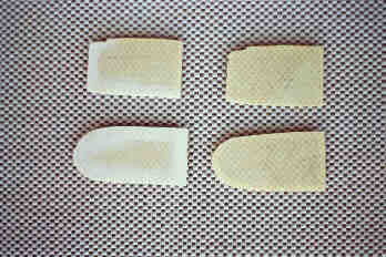 |
The prepreg closeout parts These are the 4 parts that were created from the foam patterns above. They have been tightly fit into the counterweight closeout areas and are ready for assembly to the stab. You can see the sanded areas on the parts to the left, they are for the right side of the stabilizer and the sanded sides will face into the stab. |
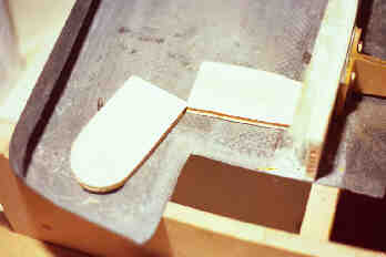
Ready for assembly Looking at the left end of the stab, the two closeout ribs await attachment to the stabilizer's bottom skin and aft spar. You can see the skin has been sanded and all that's left is to prepare the adhesive and glue the parts in. |
 |
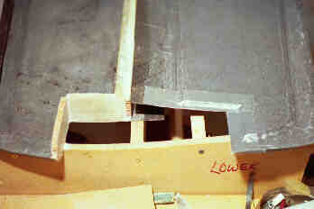 |
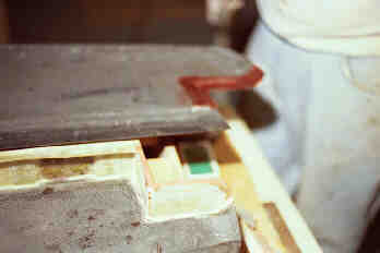
Preparing to install the capstrips The ribs have been assembled to the bottom skin with a micro mixture and they will next be bonded to it with 2-BID layups that will extend up the inside of the ribs and about an inch onto the lower skin. Additionally the outside corner formed between the two ribs will also be laminated with a 2-BID layup. Here we are getting ready to microfit the ribs to the top skin in preparation for adding the capstrips. That process, once again, calls for the addition of 3 layers of duct tape to the mating (top skin) surface and then applying a micro mixture to the edge of the ribs. The skin is then set on the mating parts and the micro mixture is left to cure. This creates a perfect imprint of the shape of the top skin in preparation for the addition of the capstrips. Once the microfit is achieved the outer two layers of duct tape are removed leaving a single layer as the release for the capstrip. |
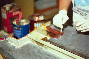
Applying capstrips to the top skin After two layers of duct tape are removed from the top skin, two layers of bidirectional cloth are applied to the remaining layer of duct tape. I'm using an acid brush to stipple them into the duct tape, removing all air bubbles in the process. |
 |
 |
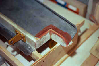
Ready to set the skin The 2-BID is now applied to the top skin and awaiting application to the stab assembly. Since these were such small layups (each was only about 4-5 inches long) I did both ends at once... this is once again the left end of the stabilizer (viewed from above the forward edge). If you look closely you can see the epoxy that has also been applied to the edges of the ribs to help insure a positive bond would be accomplished. (In case you're wondering about the color of the epoxy, as it sat in my epoxy pump the catalyst would slowly turn steadily redder, causing the mixture to take on a decidedly reddish tint. The folks at Jefco assured me that the color change would in no way affect the strength of the bonds and was probably being caused by some reaction between the chemicals in the catalyst and either the plastic container or the check valve, they couldn't be sure which.) |
The capstrips are applied Once the epoxy had been left to cure, the top skin is removed from the bottom skin and all that remains are the capstrips, firmly attached to the closeout ribs. Prior to final bonding the remaining duct tape will be removed from the inside of the top skin and the skin then bonded to the spars, ribs, and mating lower skin sections. |
 |
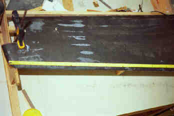 |
Getting ready for final assembly The top skin is temporarily laid into position over the bottom skin and clamped firmly into place. The yellow stripe across the leading edge is a tape measure which I used to insure that holes were drilled every one inch for the screws that would be used to hold the leading edge together during cure. The procedure was to use a 3/32" drill bit to drill through both the upper and lower leading edge skins. These size holes would allow the #6x3/8 sheet metal screws to get a good grip into the carbon fiber skin. Once all the holes have been drilled, the top skin is once again removed from the fixture and its holes were re-bored using a 1/8" drill bit. This would allow the screw to slip easily through the top skin without deforming the hole or causing a bulge that might hold the two leading edges apart. A suggestion from some Lancair-IV builders which I learned of after I had completed my closeout was to add a narrow strip of 1/4" plywood to the inside of the lower skin's leading edge... this would give the screws some additional material to bite into and is a fine suggestion, although a bit overkill in my opinion. Either method works just fine, although without the plywood backer you do need to be a bit more careful that you don't overtighten the screws and wring them out of the inner skin. |
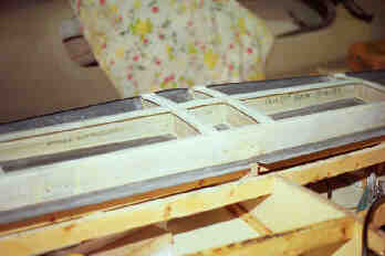
Ready to close the stabilizer All the holes have been drilled into the leading edges, all surfaces have been sanded with 40 grit paper and cleaned with methylene chloride, the existence of the required vent holes is verified, final fit checks are made and the stab is ready to be closed out. If you look closely you can see some writing on the rear of the front spar... my cousin who has been helping with the project and I have both signed our names to that spar and dated it for posterity. It's my sincerest wish that no one _ever_ gets to see those signatures. |
 |
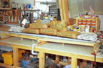 |
All glued up After measuring all mating surfaces, the required amount of Hysol structural adhesive has been mixed (I used a formula that called for .4 grams per square inch of coverage when mixed with flox, and .3 grams per square inch for areas that didn't require flox) and applied to all mating surfaces. The use of a clean caulking tube filled with the Hysol/flox mixture to apply the beads of adhesives to the tops of all spars and capstrips would really simplify its application, and I wholeheartedly recommend taking that approach when doing this large a layup. I didn't have any at the time and so used tongue depressors to scoop the mixture from the mixing cups and then as applicators. It got the job done, but not nearly as neatly or speedily as the caulking tube would. They are readily available from the folks at Stoddard-Hamilton, (makers of the Glasair and Glastar lines of kit aircraft, see my Links page), and with a little searching, may likely be available from a local source such as a large paint or building supply store. |
To insure that a good bond would be achieved between all mating surfaces I once again used my sandbags to weight everything down and a total of 360 pounds of weight is atop the structure. Once the bags were applied a visual inspection was performed around the entire perimeter to insure that some squeeze-out could be observed, indicating that an adequate amount of adhesive had been applied. In addition to the sandbags, the leading edges were screwed together with the #6x3/8 sheet metal screws, and the edge checked once again for squeeze-out. The material which was squeezed out was wiped as filler along the leading edge and shaped into fillets along the aft spar wherever possible. The entire assembly was left to set for 24 hours before removing the sandbags or the screws to insure that everything had adequate time to cure. |
|
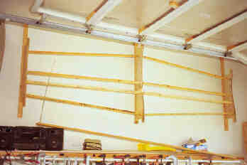
The cradle is finally put to rest After having the horizontal tail in its cradle for the past several months it was a real milestone to remove that cradle from the building bench and retire it to the wall next to the west garage door entrance to the shop. It's sort of back in service now that that assembly is complete, holding the elevators up out of harm's way while work progresses on the rest of the kit. |
 |
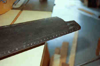 |
All screws removed from LE Now that the stab has been finally assembled, the screws are removed from the leading edge. It took a little sanding to get rid of the glue ridges that built up under the screw heads, but it was a pretty pleasant activity given all the work that had been accomplished getting the stab to this point. |
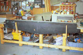
Getting ready for the final steps One of the last things that needed to be done to the stabilizer was to laminate a 3-BID layup inside the trailing edge which would tie the top and bottom skins to the spar and stiffen the entire aft assembly. I built a couple of small L-shaped brackets out of particleboard and clamped them to the building bench as supports for the stabilizer while it would be worked on in the vertical position, they can be seen here clamped to the second and fourth legs of the bench. A few shims in between the brackets and the stabilizer helped to keep the entire assembly steady for the subsequent work. |
 |
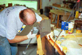 |
Inspecting the layups That's a 300 watt halogen worklight that I'm holding and using it to inspect the quality of the layups that have just been applied to that trailing edge. All things considered, it was a pretty sizeable layup (over 6 inches wide and 8 feet long), and as such it was required that each layer be applied in segments. Each lamination was then carefully inspected for air bubbles and only after the integrity of each layup had been ascertained would I continue with the next. It took several hours over a two day period to complete the entire thing, and turned out just fine. Prior to adding those layups all of the hinge bracket screw holes had been plugged with modelling clay to keep the epoxy out of the nutplates. |
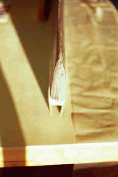
Preparing for the last of the layups With the trailing edge laminated all that remained was to prepare the stabilizer tips for their closing layups. Here is one of those tips all sanded and waiting for the 2-BID closing layup that will pretty much lay this component to rest. |
 |
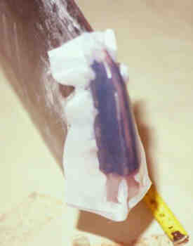 |
Layup is applied The final layups have been completed on both stab tips and all that's left is for them to dry. To provide a bit of a smoother surface I chose to use peel ply (the white cloth seen here) which will be removed after the epoxy has cured. |
Well, that about covers it for the building of the horizontal tail. Naturally there is still a bit of work to be done on it, such as applying the hinges and getting all the body work done... but that can wait for a time later in the project. I'm very pleased that I chose to start this project with this assembly, as it provided the desired slope to the learning curve, gave me great confidence in dealing with fiberglass layups and many of the other processes that will be encountered during the building of the rest of the project. It consumed a bit more time than I had hoped it would (460 man hours, or 290 hours on the clock), but it was well worth taking the time to get it done right. But now... it's time to move on to the big parts! |
|